Introduction
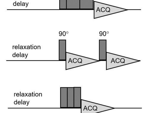
One of my colleagues recently notified me of a novel pulse sequence published in The Journal of Magnetic Resonance. The experiment uses the so-called TRIP (Triple-Pulse) excitation scheme, which is a series of three pulses with appropriate phase cycling to eliminate background signal and probe ringing effects [1]. The reason why the article draws my attention is that I had coded and tested a background suppression experiment named EASY (Elimination of Artifacts in NMR SpectroscopY) [2–3] in the past. Why should you care? I am going to talk about the origin of background signal in solid-state NMR and give you tips on how you can recognize and suppress background signal.
Why background suppression in solid-state NMR
Solid-state NMR probes, rotors, rotor caps and spacers are made of materials which may and usually produce background signal in 1H, 13C, 19F and other solid-state NMR spectra. If the sample of interest gives an intense signal, the background signal might be negligible in comparison and difficult to see. However, if the sample of interest gives a weak signal, the background signal might be a nuisance. It might be wrongly assigned to the sample of interest, it might distort quantitative information, and it might complicate phase and baseline correction. For these reasons, it is important to know whether your probe and rotor has any background signal, and if so, it is desirable to suppress the background signal or be aware of it, at least.
How to recognize background signal in solid-state NMR spectra
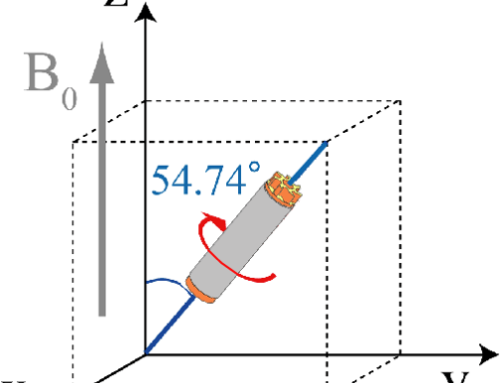
The probe background signal is typically broad and has no spinning sidebands, because it mostly comes from materials used in construction of spinning modules. For this reason, these parts do not spin under the Magic Angle. The background signal of rotor caps is usually very weak in comparison to the probe background signal.
You can selectively observe the background signal of your probe and rotor (including rotor caps) if you run an experiment on an empty rotor. The probe background signal can be selectively observed by running an experiment with an empty probe. In the ideal case, you should observe no background signal at all. If you observe some background signal, it can then be subtracted from the signal of your sample of interest. However, it is necessary to run two consecutive experiments: one with the empty rotor and one with the sample in the rotor. Even if you set identical acquisition parameters, the subtraction might not be perfect, because probe tuning and hence the excitation pulse will most likely be affected. For this reason, this classical approach is not very efficient and popular.
Background suppression using special pulse sequences
Various pulse sequences have been designed to eliminate background signal in MAS (Magic Angle Spinning) experiments [1-9] without the need for two separate experiments. Some of these pulse sequences, such as TRIP and EASY mentioned above, also suppress the artefacts caused by acoustic ringing. Acoustic ringing is out of the scope of this post; however, the interested reader is encouraged to read the original articles on TRIP and EASY and the articles referenced therein. It is worth of mentioning that background signal is a problem associated with direct polarization techniques such as MAS (Magic Angle Spinning) and DDMAS (Dipolar Decoupling Magic Angle Spinning). CPMAS (Cross Polarization Magic Angle Spinning) efficiently suppresses background signal. The reason is that the Hartmann-Hahn matching condition is only met in the active volume of coil.
Examples of spectra
Figure 1 shows 1H MAS spectra collected on a rotor filled with L-tyrosine hydrochloride at 17 kHz MAS on a JNM-ECZ500R spectrometer. The sample was packed without spacers. The blue spectrum was collected conventionally, while the green spectrum was collected with the DEPTH background suppression sequence [4–5]. First of all, I would like to draw your attention to the baseline. In the absence of the background suppression the blue spectrum contains a broad background component under the spectrum of the sample. As a result, the dips between the isotropic peak and spinning sidebands do not go down to the baseline. This is improved in the green spectrum where the broad background component is removed by applying the DEPTH sequence. You have probably noted that the signal of the sample is somewhat smaller in the green spectrum. This is due to the multipulse nature of the DEPTH sequence. It suppresses the signal of sample which is not in the active volume of the coil. However, in this case, the loss of signal is rather negligible.

Figure 1. 1H MAS spectra of L-tyrosine hydrochloride collected at 17 kHz MAS without background suppression (blue) and with DEPTH background suppression (green).
Figure 2 shows 1H MAS spectra collected on an empty zirconia rotor. The blue spectrum exhibits a relatively strong, broad signal which comes from the probe. The green spectrum was collected with the DEPTH sequence and shows excellent suppression of the background signal.
![]()
Figure 2. 1H MAS spectra of empty zirconia rotor collected at 5 kHz MAS without background suppression (blue) and with DEPTH background suppression (green).
Figure 3 shows 19F MAS spectra collected on an empty zirconia rotor. Obviously, the probe also contains materials containing fluorine. However, the DEPTH sequence also did a great job of suppressing the background here – the green spectrum is almost flat.
![]()
Figure 3. 19F MAS spectra of empty zirconia rotor collected at 5 kHz MAS without background suppression (blue) and with DEPTH background suppression (green).
Finally, the blue spectrum in figure 4 shows 13C DDMAS spectra acquired on an empty rotor. The background signal is very broad and covers the entire range of 0-220 ppm. With the DEPTH sequence, it is also possible to eliminate the 13C background signal.
![]()
Figure 4. 13C DDMAS spectra of empty zirconia rotor collected at 15 kHz MAS without background suppression (blue) and with DEPTH background suppression (green).
Conclusions
I have discussed the origin of background signal in solid-state NMR and shown examples of 1H, 13C and 19F spectra with and without background suppression. I have also explained why we need to be able to recognise background signal and how to suppress it. That’s all for this post.
If you wish to learn more on background suppression in solid-state NMR, please read the second post on practical aspects of DEPTH, EASY and TRIP.
And why not try JEOL JASON software for yourself? Discover how its advanced data processing and analysis tools make it easy to get great results from solid-state and many other NMR datasets.
If you wish to know more about JEOL ECZ Luminous NMR spectrometers and JEOL solid-state NMR probes, click the links. A brochure on JEOL solid-state NMR is available here.
References
[1] F. Wang, S.K. Ramakrishna, P. Sun, R. Fu, J. Magn. Reson. 332 (2021) 107067.
[2] C. Jaeger, F. Hemmann, Solid State Nucl. Magn. Reson. 57-58 (2014) 22-28.
[3] C. Jaeger, F. Hemmann, Solid State Nucl. Magn. Reson. 63-64 (2014) 13-19.
[4] M.R. Bendall, R.E. Gordon, J. Magn. Reson. 53 (1983) 365-385.
[5] D.G. Cory, W.M. Ritchey, J. Magn. Reson. 80 (1988) 128-132.
[6] J.L. White, L.W. Beck, D.B. Ferguson, J.F. Haw, J. Magn. Reson. 100 (1992) 336-341.
[7] Q. Chen, S.S. Hou, K. Schmidt-Rohr, Solid State Nucl. Magn. Reson. 26 (2004) 11-15.
[8] J. Feng, J.A. Reimer, J. Magn. Reson. 209 (2011) 300-305.
[9] S. Odedra, S. Wimperis, J. Magn. Reson. 221 (2012) 41-50.